

Blog
Injection Tooling for PEI (Ultem™): Engineering Solutions for Critical Molding Failures

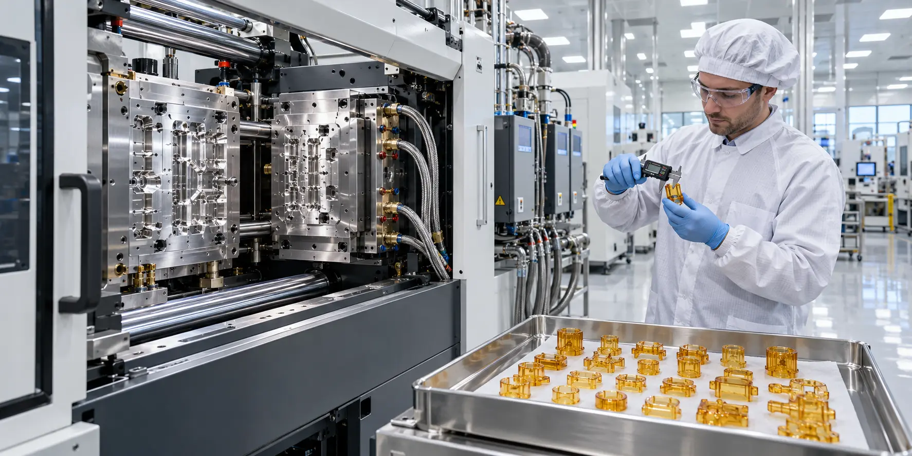
Injection Tooling for PEI (Ultem™): Engineering Solutions for Critical Molding Failures
Polyetherimide (PEI / Ultem™) delivers exceptional yield strength, flame resistance (UL94 V-0), and continuous service up to 170°C.
However, molding PEI requires extreme melt temperatures (360°C–400°C), tool temperatures exceeding 150°C, and high injection pressures (1500–2000 bar). At these thresholds, small thermal gradients and shear imbalances create severe hidden defects that standard dimensional inspections fail to catch.
Below is an engineering analysis of the four primary failure modes encountered in high-reliability PEI molding, along with our validated tooling countermeasures.
1. Latent Stress-Cracking (Part Failure During Assembly)
- The Problem: Components pass initial CMM inspection but crack weeks later during torque assembly, press-fitting, or solvent wipe-down (e.g., IPA in medical/semi applications).
- The Root Cause: Excessive pack pressures freeze uncoiled polymer chains under stress. When exposed to chemical agents or cyclic loads, this frozen-in orientation stress releases catastrophically as Environmental Stress Cracking (ESC).
- Our Tooling Countermeasure:
- Low-Shear Diffusion Gates: Parabolic transitions taper down melt velocity, keeping shear rates strictly under 10,000 s⁻¹.
- Cavity Pressure Sensors: Piezoelectric sensors at the gate trigger real-time, dynamic pack-pressure switchover, preventing over-packing at the molecular level.
- The Engineering Result: Zero delayed cracking; parts retain full chemical resistance and structural ductility in the field.
2. Skin-Core Delamination (Surface Flaking in Cleanrooms)
- The Problem: Microscopic polymer scales peel off the molded surface during automated handling, ultrasonic cleaning, or fluid flow—causing fatal particle contamination in semiconductor tools and surgical fluid paths.
- The Root Cause: High shear through restrictive gates degrades the melt boundary layer. Rapid thermal quench at the cavity wall separates the frozen outer “skin” from the molten “core.”
- Our Tooling Countermeasure:
- Rheological Vector Polishing: Runners and gates are micro-polished parallel to melt flow to Ra < 0.05 μm, eliminating shear-induced boundary turbulence.
- Short-Land Sub-Gates: Gate lands are held to ≤0.8 mm to minimize high-shear residence time.
- The Engineering Result: Homogeneous morphology across the wall thickness; 100% flake-free surfaces certified for Class 100 cleanroom environments.
3. Molecular Density Drift (Optical Distortion & Micro-Leaks)
- The Problem: In fiber-optic components (e.g., MT ferrules) and hermetic sensor housings, parts meet 2D tolerances but fail light transmission tests, exhibit optical distortion, or fail helium mass-spectrometer leak checks.
- The Root Cause: A thermal variance of just 3°C to 5°C across cavity inserts alters localized volumetric shrinkage and molecular density, causing internal micro-voids and refractive index drift.
- Our Tooling Countermeasure:
- DMLS Conformal Oil Channels: We employ Direct Metal Laser Sintering (3D printing) to build organic, conformal heating channels where drilled lines cannot reach.
- Tight Thermal Control: Cavity surface temperature delta is held within ±1.5°C across the entire profile.
- The Engineering Result: Isotropic molecular density, uniform refractive index, and zero vacuum micro-voids.
4. High-Temperature Tool Seizure (Galling at 165°C)
- The Problem: Slides and lifters that stroke smoothly during cold setup gall, bind, or seize completely after 2–3 hours of continuous production.
- The Root Cause: Thermal expansion mismatch at 165°C steel temperatures. Under 1800 bar cavity pressure, microscopic parting-line deflection allows low-viscosity PEI melt to flash into slide clearances, welding slides shut.
- Our Tooling Countermeasure:
- Dynamic Thermal Offsets: All moving components are machined with pre-calculated thermal expansion clearances designed specifically for 160°C equilibrium.
- Dissimilar Metallurgy: Through-hardened tool steel (S136 / Elmax at 54 HRC) is paired with Ampco 21 aluminum-bronze wear plates and PVD DLC coatings.
- The Engineering Result: Smooth dynamic actuation over 500,000+ cycles with zero galling or tool maintenance downtime.
Typical Tooling Specifications for PEI Components
| Parameter | Our Standard Specification |
| Cavity & Core Steel | Uddeholm Elmax / Stavax S136 / Bohler M390 (Through-hardened to 52–54 HRC) |
| Mold Temperature Strategy | High-pressure oil channels (up to 180°C) with 15 mm composite insulation plates |
| Venting Precision | 0.025 mm (±0.003 mm) micro-vents on full perimeter |
| Surface Finish | SPI A-1 to A-3 optical polish; PVD DLC coatings on dynamic wear surfaces |
| Quality Documentation | Complete Moldflow report, steel certification (CoC), and full CMM inspection |